400MHz clock generator for the AD9951
Clock generator at 400MHz
for the 150MHz network analyzer

A quartz cristal oscillator drives a buffer NC7WZ16. A 400MHz band-pass filter selects the fifth harmonic.
This filter is made of four resonators. These resonators are made of PC board traces and surface mount capacitors.
A capacitors (C5) at the output of the NC7WZ16 is tuned with the inductance of the trace (between the buffer and the first resonator).
C5 must be adjusted to have the highest signal amplitude at the output of the filter. This adjustment is not critical.
This filter was design with the software « freeEM3DS« .
This clock is connected to two AD9951 by the mean of coax cables. The characteristic impedance of these cables is 50 ohms or 75 ohms.
The printed circuit board material is FR4 ; the thickness of the PC board is 1.6mm.
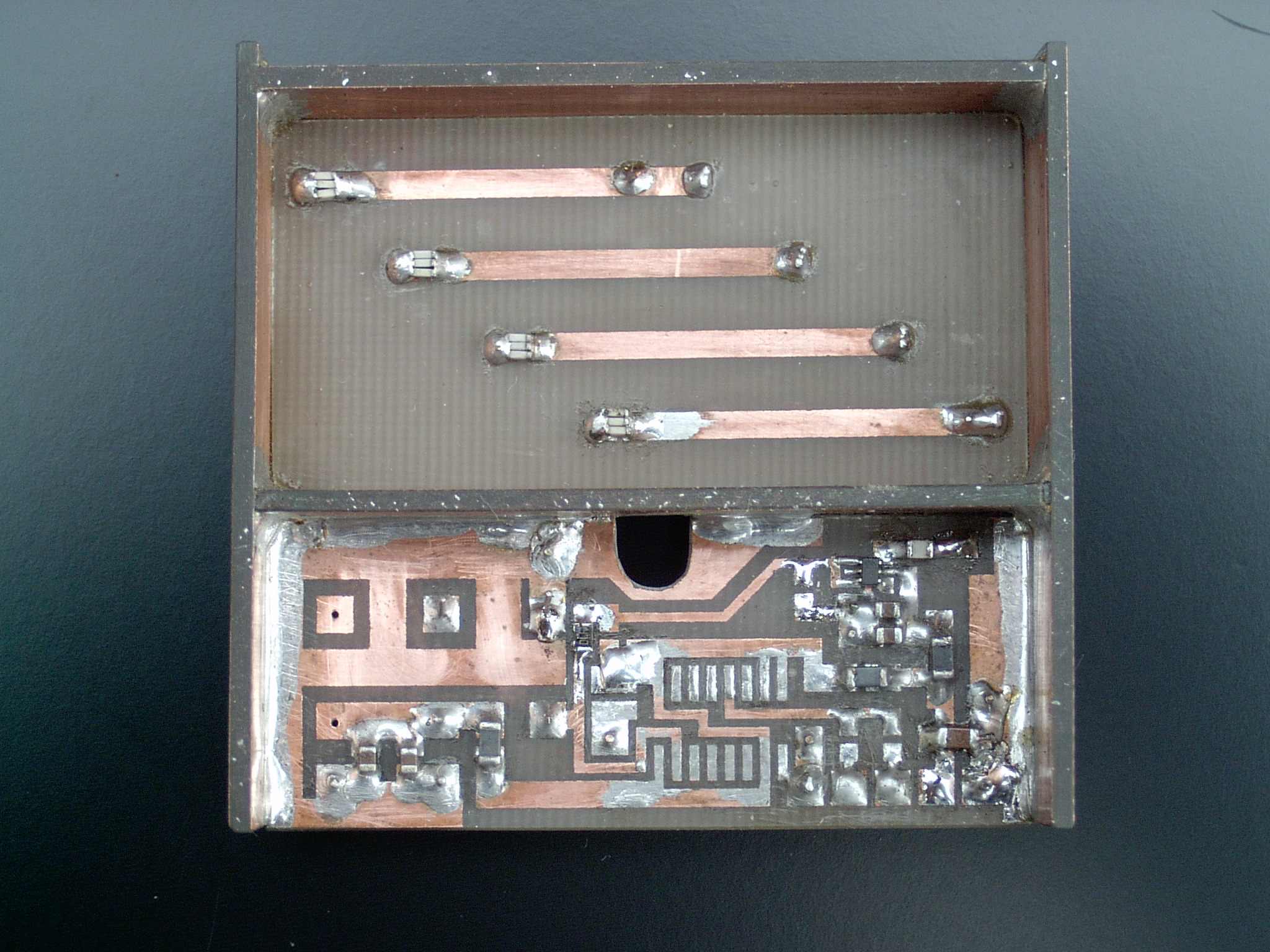
Top view of the filter
Above the filter, a lid must be installed, the distance between the PC board traces and the lid is 10mm.
The presence of the lid does not change the amplitude of the output signal.
At the output of the 80MHz oscillator, there is the possibility to add a 74AC161 (the 74AC161 is not loaded).
Each capacitor of the resonator is made of 3 capacitors ( in parallel to reduce the ESR).
The 80MHz oscillator is a through-hole component, the oscillator is loaded on the ground plane side.
The connection between the ends of the resonators and the ground plane is made of two small wires (diameter 0.6mm).
A small wire connects the capacitor C5 to the first resonator. This connection is on the ground plane side.
The diameter of the conductor is 0.4mm, the diameter of the wire is 0.7mm (insulation material : teflon).
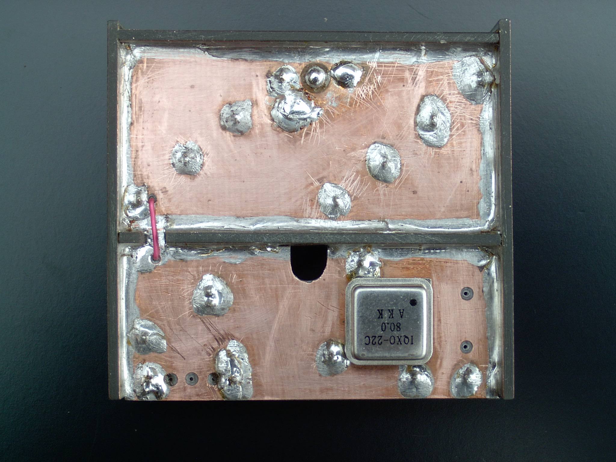
bottom view of the filter
Under the small red wire (at the input of the first resonator), a small sheet of copper is used to preserve the continuity of the ground plane.
The output of the filter is under the 4th resonator.
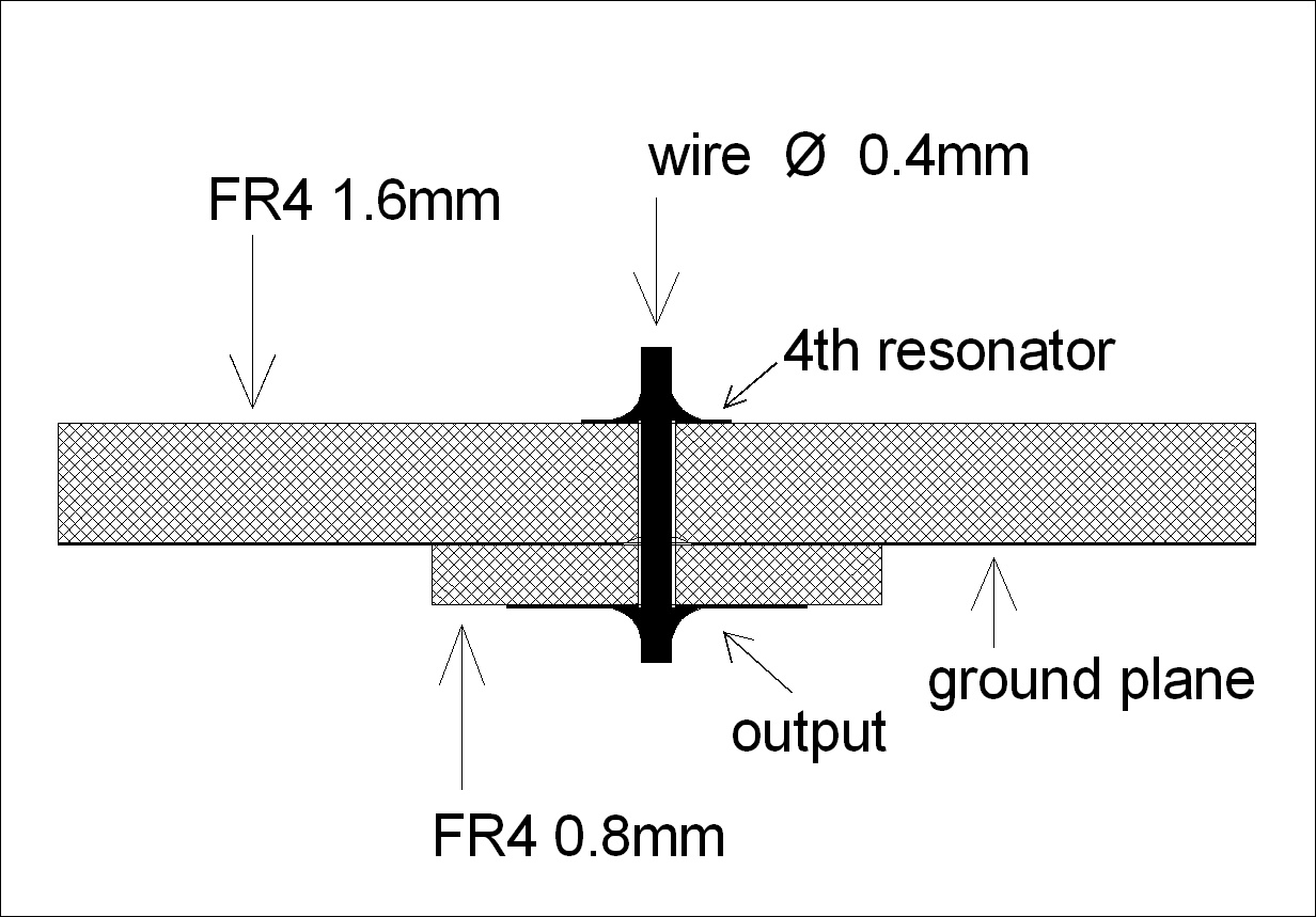
A drawing to show the output connection
A very small PC board is used to keep the ground plane under the 4th resonator.
Measurements
With a load of 56 ohms on both outputs, the amplitude of the signal is 500mV (peak to peak).
If one does not have the equipment to measure at the frequency of 400MHz, one can build a small detector with a schottky diode. We use an HSMS2822 diode, a 100nF capacitor (CMS) and a DC voltmeter, if the length of the connections is short, the bandwidth of the detector is higher than one GHz.
To calibrate the detector , one can use a simulation (with the LTspice software), or one can calibrate the detector at a lower frequency.
To increase the amplitude of the signal (at 400MHZ), one can change the value of the loads (for example : change from 56 ohms to 68 ohms).
To increase the amplitude, it is also possible to use the two buffers of the NC7WZ16 ( in parallel).
To have strong odd harmonics and weak even harmonics, the duty cycle of the 80MHz signal must be 50%. If needed, it is possible to add a pull-up resistor or a pull-down resistor at the input of the NC7WZ16 to improve the duty cycle.
 Frequency response of the 400MHz filter (simulation)
The printed circuit : filter_400MHz.pdf